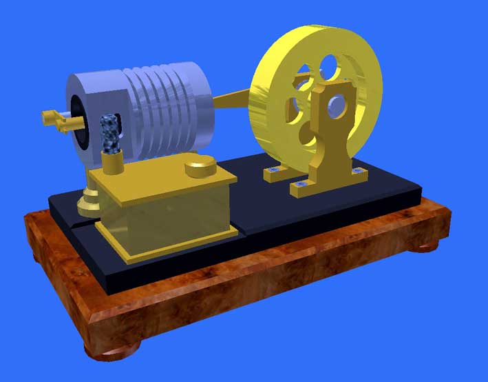
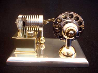
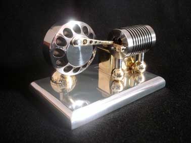
Improved version (March 2011).
Mainly because the original design suffers from serious pollution due to rust deposits in the cylinder I changed the design. The main changes are:
- Cylinder made from stainless steel instead off pearlitic grey cast iron;
- Piston and internal valve made from graphite instead of pearlitic grey cast iron;
- Enlarged diameter of cylinder bore, piston and valve; from 18mm to 22mm;
- Somewhat further simplifying of the mechanical construction.
With this the absence of rust and the self greasing property of graphite now ensure a 100% reliable performance with hardly maintenance or not at all. Enlarging the cylinder content with about 50% makes the power significant greater, contributing significantly to a less critical engine behaviour.
The number or parts is reduced somewhat and some parts are more distinct such as the valve catcher and the stroke pin behind the piston. Now it suffices to only fix this stroke pin on the pusher rod on the right place so there is a very small clearance when the piston is on its ultimate back position.
A vacuum engine with internal head valve
In fact the principle of a vacuum engine is very simple; see page "Working principle". However the classic construction with the external head valve (slide) that closes and opens the hole in the cylinder every cycle, is proportionally complex. But above all, the adjusting of this valve with all driving mechanisms is rather critical. Small deviations easily result in a bad or not running engine:
1. A too high spring pressure on the cams disc acts as a break on the engine. On the other hand, if this pressure is too low the system starts floating, whereby the timing of the head valve becomes incorrect. So adjusting the right spring pressure on the cam disc is rather critical;
2. The spring pressure transverse to the movement of the head valve is critical to. Too high means detrimental friction, too low causes a leakage between the surface of the valve and the cylinder;
3. If the working piston moves to the cylinder head (as a result of the under pressure) the flame gasses are repressed at the same time. Some time before the piston reaches the cylinder head the pressure in the cylinder becomes equal to the open air pressure. It grows to a restraining overpressure if the cylinder hole is opened too late by the head valve. On the other hand, freeing this hole too early leads to a loss of engine power. So, one has to determine experimentally the width of the cam because this stipulates the movement pattern of the head valve. Besides that the moment whereby the pressure equals the open air pressure depends also to the cylinder temperature. This temperature varies but the movement of the head valve isn't.
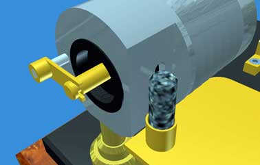
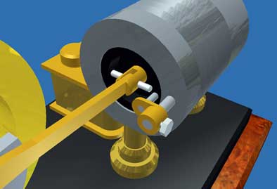
These disadvantages brought me the idea to implement a internal head valve instead off an external one. In fact this is a second piston that makes a small stroke, thereby closing and opening the cylinder hole on the inside in stead off on the outside of the cylinder. This construction makes it also possible to drive this valve directly by the working piston in a very simple way.The working principle of this design
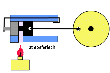
If the working piston has arrived to the most right position it has pushed the head valve over the cylinder hole by means of the small pusher that can move horizontally through a bore in the outside cylinder wall. At that moment the hot flame gasses are locked-up in the cylinder and start to cool down. This causes a partial vacuum in the cylinder and consequently the force on the working piston that pushes it back to the left. In fact this delivers the working stroke of the engine. This vacuum also works on the internal head valve and keeps it in the right position, so that the hole in the cylinder stays in the closed status.
If the working piston moves to the left the gasses in the cylinder are repressed as well. At the moment this pressure becomes equal to the open air pressure the head valve is automatically pushed open. So It works also as an automatic relief valve so that counteracting pressures never can occur. If one looks well this effect is visible in the animation above.
A small cam on the working piston pushes the head valve mechanically to the ultimate left position when the working piston is driven further by the flywheel. With that the way is cleared for the flame gasses to enter the cylinder when the working piston moves to the right again due to the flywheel effect. This cycle repeats itself when the working piston has arrived again in the ultimate right position.
Advantages of this internal head valve design
This design has several advantages compared to the current construction with external head valve:
1. The rather precarious mechanism with camshaft, tumbler and springs is eliminated completely and, with that, also the critical adjustments of the cam disc, the spring pressure on cam and on the head valve and the timing of this mechanism;
2. The airtight sealing of the internal head valve is simply a matter of making a good fitting in the cylinder just like the working piston;
3. A restraining overpressure in the cylinder cannot occur because the head valve opens the cylinder hole at the moment the pressure equals the open air pressure;
4. The friction of the internal head valve in the cylinder is considerable lower than the that of the complete mechanism for the external valve and no spring pressures must be gained;
5. The temperature of the internal valve is lower than that of the external one. The last is radiated directly by the burner, as well as the spring that must keep this external valve tight to the surface of the cylinder;
6. The adjustment of the parameters to run the engine is implicit anchored in the design. In other words, there is nothing left to adjust at all and nothing can drift away;
7. Because of symmetry this engine runs to the right as well as to the left. May be not an explicit advantage, be remarkable anyway;
8. This design is extremely simple and robust with a minimum of accessories which are easy to make one by one. It is a nice model for not very experienced model builders.Some specifications.
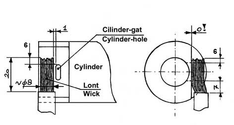
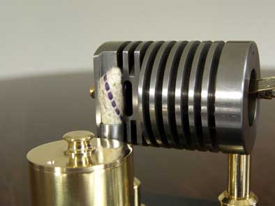
-The piston and the internal head valve are made out of grahite. The most important reason is that that this material is self greasing and it has a low temperature expansion coefficient. This avoids jamming of the piston and/or the head valve in the cylinder. For the cylinder I used stainless steel to avoid any rust deposits. The bore in the cylinder must be exactly cylindrical and smooth. The diameter of the piston as well as the head valve must be very little smaller (0.03mm or less) than the diameter of the cylinder bore, so that they can move with very low friction and yet sealing well against the open air.
- The pusher for the head valve is a steel rod with diameter 3 mm and glides easily in a bore through the cylinder wall. On one side there is a catcher, driving the internal valve with some free space; this to avoid possible wriggling. On the opposite site of the pusher a small accessory is attached against which the piston strikes in the utmost right position to close the hole in the cylinder by the internal valve. This "striker" must be fixed to the rod with a 2mm screw so that there is a very small clearance to the piston when that is in its ultimate right position. Only unscrewing this striker makes it possible to easily dismantle the rod, the piston and the head valve, for instance to clean this parts and the inner surface of the cylinder if necessary.
Adjustment of the engine.
As said there is hardly anything to adjust to this engine. The once-only adjustment concerns fixing the striker at the right position of the pusher rod. When this is done right you see the following when turning the fly wheel slowly by hand:
In the utmost right position of the piston: the internal valve is pushed completely over the flame hole in the cylinder with about 1mm overlap.
In the utmost left position of the piston: the valve is pushed by the cam on the piston so that it opens the flame hole except for the last 1mm. If the engine runs the valve will overshoot so the flame hole will be opened completely then.
Adjustment of the burner wick.
All vacuum engines are very sensitive for the size of the flame and its position in front of the cylinder hole. It is important to avoid false cold air to be sucked into the cylinder together with the flame gasses. It shall be clear that this easily happens with a strongly waving flame as a result of draught. Mostly always the engine stops running in that case immediately. But this can happen as well with a flame that is too small. It is my experience that the width and the height of the spirits flame must be about two times as big as that of the cylinder hole.
Remarkable is the effect of the position of the flame in front of the cylinder hole. It is always necessary to position the flame some millimetres away from the centre of the cylinder hole in the direction of the cylinder head. Apparently the flame gasses are sucked-in under a certain angle.
Finally, the distance of the flame to the cylinder hole is of importance to.
So, before fixing the spirits burner on the engine one has to find the optimal burner position by moving it by hand in front of the cylinder hole and determine when the engine runs best.
Industrial ethanol (98%alcohol) is preferable above spirits if one can obtain it. The flame temperature is fairly higher and it causes less sediment on the piston, on the head valve and on the inner surface of the cylinder.The engine performances.
-The engine starts 100% reliable immediately or at least within one minute after the burner is lightened. In this first minute condense water from the flame gasses that can slow down the engine somewhat disappears when the cylinder heats up.
-As said, this vacuum engine has no preference for a revolution direction. This is a direct consequence of the fact that the usual cam disc, that shows asymmetry in the cycle diagram, is missing in this design.
-The max. revolution speed is 400 to 500 rpm if everything is adjusted well.Video:
Finally.
Because of its extreme simplicity this engine may not look very spectacular to an unsuspecting spectator. But I assume that this unique design shall be valued by many connoisseurs in the small world of vacuum engine builders.Drawing plan
I made a CAD drawing plan for this flame eater that is available for every-one interested; click here for a request.
Trouble shoot check list
See also demo part at the end of the video above.
Sometimes I am asked what to do if one has problems to let this engine run.
To find the causes and solve possible problems I made the following trouble shoot list to be followed systematically in the given order. The values in it are related to those of my engine that runs very well with (max) speed of 400 to 500 rpm:
1. The engine must run slightly
One has to realize that the power of Flame-Eaters is relatively low. The dynamic under pressure that occurs in the cylinder during the cooling-down of the sucked-in flame gasses is not more than some tenths of an atmosphere. That means that mechanical frictions must be as low as possible. Furthermore a 1-cylinder flame-eater is powerless during the suck-in stroke so the absorbed rotation energy in the fly wheel must keep the engine running during that stroke.Some friction tests with cold engine and without the flame:
- Push the flywheel firmly by hand;
- The flywheel disconnected from the piston rod must keep running for 1.5 to 2 minutes;
- With only the piston connected the flywheel must keep on running for 15 to 20 seconds;
- With piston, internal valve and pushing rod connected the engine must keep running for 5 to8 seconds.
See also the last demo part of the video above.
If there is a strong non-conformity in a negative sense there is some unacceptable friction in the system. Possible causes and solutions are:
- There are combustion residues on the piston, internal valve and inside cylinder wall. This can be the case after some runs with normal spirits.
Clean the piston, the internal valve and the cylinder wall with a plush free cloth and some cleaning solvent. Wipe everything dry with a clean piece of cloth and repeat the friction test as described above.
-The fitting of the piston and/or the internal valve in the cylinder is to close.
Polish the piston and valve with some fine polishing paper or with very fine grinding paste in the cylinder.. Clean everything thorough and repeat the friction test.
- The pushing rod is wringing.
Take care that there is some space between the valve catcher and slot in the pin that is screwed in the internal valve So the valve must move as a result of a "pick-up" movement of the pushing rod.
2. The air-tightness of piston and internal valve
The piston and the valve must move very smoothly in the cylinder but on the other hand they must fit almost air-tight in the cylinder without any oil. Therefore the bore in the cylinder must be smooth and exactly cylindrical. The diameter differences over the bore length mustn't be more than 0.02mm. You can realize this rather easily by reaming the cylinder bore manually with ample oil , turning around the cylinder several times with the same reamer adjustment until the reamer can pass easily through the bore. Then adjust the reamer a fraction wider and repeat this treatment again and again until you cannot measure hardly any diameter difference anymore, at least less then 0.02mm. This way of working can compete with real honing and is a good alternative if you don't have honing equipment.
The clearance between the cylinder and the piston and valve must not exceed 0.03mm. After you made the cylinder bore as described above lathe the piston and valve exactly cylindrical and smooth until the fit well in the cylinder bore.
Check the air-tightness of the piston and the internal valve as follows with a cold engine and without a flame:
- Put the piston in the utmost right position;
- Push the internal valve in the utmost right position also whereby the cylinder hole is closed;
- Move the piston slowly to the left by rotating the flywheel. As a result the overpressure that occurs immediately in the cylinder will push the internal valve to the left until it just opens the hole in the cylinder. You can see a very narrow cleft through the cylinder hole right from the valve. If the piston is moved further to the left the valve don't move anymore because the overpressure has disappeared.
If the valve don't move at this test there is a too great leakage along the piston and/or the valve. Then the only remedy left is to make a new piston and/or valve.
3. The materials for cylinder, piston and valve.
With the present version I made the cylinder from stainless steel and the piston and valve from graphite to avoid any rust and for the self greasing properties of graphite. I can't exclude that with a stainless steel piston and valve one can obtain comparable good results, but grahite is preferable if one can obtain that.
Never oil the piston or valve. Even with the thinnest oil there will be more friction and the oil will degenerate fast due to the high flame temperatures leaving a fatal moisture film on the surfaces.
4. The adjustment of the flame
A flame-eater only can run if only the flame gasses are sucked in. All flame-eaters are very sensitive for this ! So it is very important to avoid false and cold air is sucked in together with the flame gasses
- The flame must overlap the cylinder hole significantly; see sketch below.
- Somewhat remarkable but very important is that the center of the flame must be positioned 5 to 6 mm left from the center of the cylinder hole. Most probably reason is that the flame gasses are sucked-in under some angle;
- A fluttering flame due to air draft is fatal; flame-eaters mostly stop running immediately in that case because false and cold air is sucked-in then together with the flame gasses.
- The effects of different possible positions of the flame in front of the cylinder hole are dramatic! That's why I did numerous experiments to find the optimal position in this case. The sketch below and pictures on the right of this page show the result with what the engine runs very reliable and with a speed of 400 to 500 rpm.
Remarkable is the fact that the wick must lay against the metal of the cylinder (dimension "0") and that the centre of it is some 5 mm left from the cylinder hole. You can see clearly that the flame is sucked in nicely and apparently without taking cold false air with it. This position makes the engine run very reliable with speeds between 400 and 500 rpm.
So the burner must be adjusted in the horizontal as well as in the vertical direction until this situation is achieved.
With a running engine it is sometimes possible to find a further more optimal position of the cotton wick by bending it in one direction or another with a tweezers.
5. Water condensation
When the fuse is lit, some condensation water will form against and in the cold cylinder during the first minute. It is recommended to leave the engine stationary during this time with the piston and slide in their rearmost position. This condensation water will then disappear during the heating of the cylinder.6. The fuel for the burner
The performance and the reliability of the engine can be significantly improved by using pure ethanol instead of spirits. The heat value of ethanol is considerable higher and its flame is less polluting compared to spirits that, except for ethanol, contains about 10% water, 2% methanol and coloring agent.
Naturized alcohol (=96 to 98% ethanol) can be easily obtained in drug stores (at least in Holland) for some 12 Euro's per liter.
!! Never use 100% methanol because it is very poisonous !!7. Engine maintenance
Despite the use of stainless steel and graphite it always can happen that the engine will be polluted for one reason or another. In that case remove the piston and the valve and clean everything with cloth or paper impregnated with some solvent like WD40. Make everything dry after that.This looks quite a list of requirements but they are all very well achievable. If one meet this requirements this engine will run pretty well like a sewing machine with a speed of 400 to500 rpm !
Nice working-out from Jeroen Jonkman:
Wonderful replica made by
Lorenzo Libero:
Nice work students
WICO campus Belgie:
Brilliant replica made by
Heiko Strassberger:
Nice replica made by
Cristobal Jamarillo:
Nice replica made by
Josef Drapak: